From CAD Geometry to Manufacturable Design: Automating DFM Checks on Reinforcement Ribs
Discover how Dessia transforms reinforcement rib recognition into intelligent 3D Design for Manufacturing verification. From understanding CAD geometry to applying engineering rules and building reusable AI agents, explore how CAD-aware intelligence helps engineers verify manufacturability across complex designs.
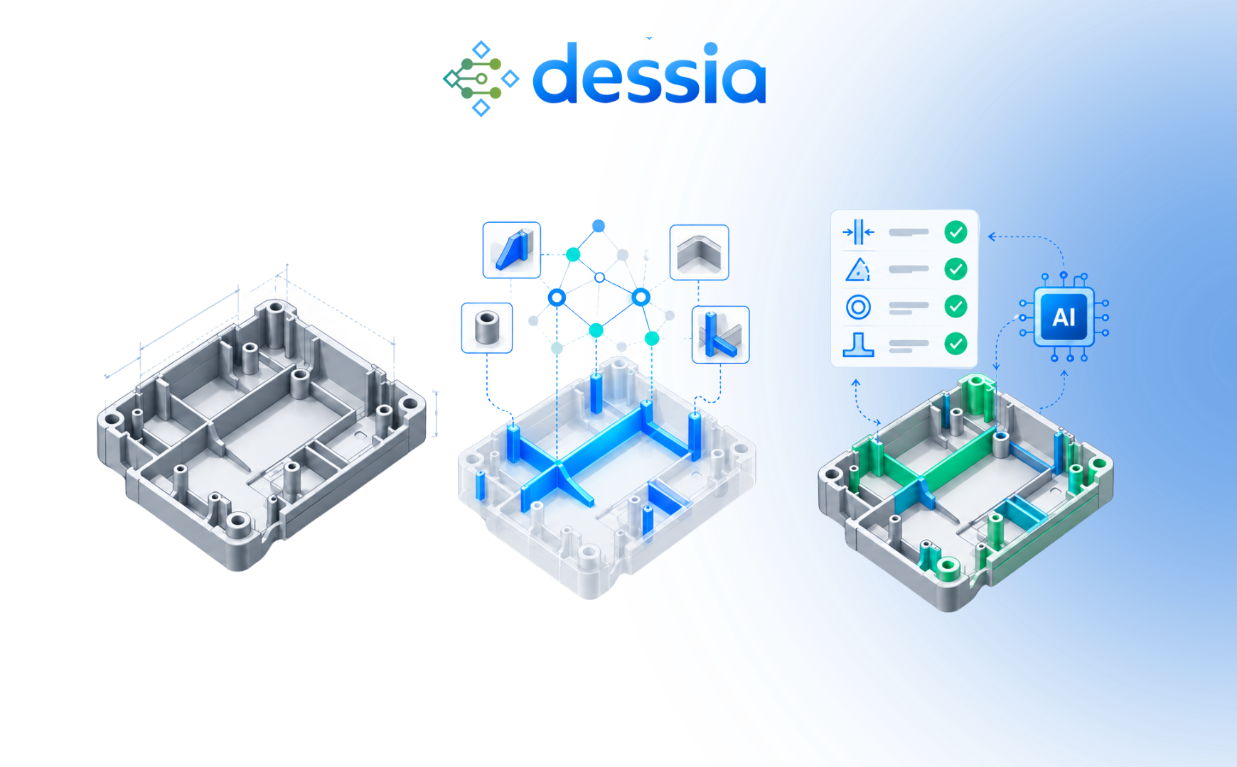
How Dessia turns complex CAD geometry into structured engineering features for scalable DFM verification
Design for Manufacturing depends on a simple principle: manufacturing constraints should influence the design before problems reach production.
In practice, however, applying DFM rules consistently across complex CAD models is far from simple.
A reinforcement rib may be obvious to an engineer looking at a plastic housing or structural tray. In the CAD model, that same rib may be fragmented across several surfaces, connected through fillets and represented as part of hundreds of BRep faces.
Before software can verify whether the rib respects manufacturing rules, it first has to understand that the rib exists.
That was the challenge Dessia set out to solve.
The challenge: DFM rules cannot be applied to geometry the software does not understand
Consider the design review of an injection-molded plastic component.
Engineering teams may already have internal Design for Manufacturing rules defining acceptable rib thickness, relationships between rib and wall thickness, junction configurations or other manufacturing constraints.
The rules themselves are not necessarily the difficult part.
The difficulty is automatically identifying the geometry to which those rules should apply.
A typical reinforcement rib includes two opposing surfaces defining its thickness, additional surfaces forming the wall, a supporting base and often fillets joining the different regions.
But simple geometric searches quickly generate false positives.
A groove can contain thin surfaces. A pocket may contain opposed faces. Two unrelated surfaces can happen to be parallel and close together.
At the same time, one physical rib can be divided into several CAD faces because of modelling history, intersections or Boolean operations.
For an experienced engineer, interpreting this geometry is almost instantaneous.
For software, every relationship has to be reconstructed explicitly.
The real challenge was therefore not simply: Can we detect thin surfaces?
It was: Can we reconstruct the engineering feature behind the CAD geometry reliably enough to apply Design for Manufacturing rules to it?
The solution: transform raw CAD into engineering features
Dessia developed a geometric recognition method capable of reconstructing reinforcement ribs directly from complex CAD geometry.
Instead of analyzing CAD faces independently, the method studies how those surfaces relate to one another.
The CAD topology is represented as an Attributed Adjacency Graph, or AAG.
Each CAD face becomes a node. Shared edges connect those nodes, while the relationships between neighbouring surfaces are characterized as convex, concave or smooth.
This creates something much more useful than a list of surfaces.
It creates a map of how the component is constructed.
The Designer can then identify potential rib walls, analyze their surrounding topology, follow connections through fillets and determine whether the surfaces actually form a reinforcement feature.
The objective is not to recognize one predefined CAD pattern. It is to understand the geometric logic behind the feature.
That distinction is essential because two engineers can model the same physical rib differently while its engineering and manufacturing function remains identical.
How the recognition works
The method follows a progressive process;
First, it identifies surfaces that could potentially form the two sides of a reinforcement rib. Their normals should point in opposite directions, and the distance between them should be compatible with a thin wall.
The search also considers surfaces that are effectively flat but represented as BSplines rather than mathematical planes, which is common in real industrial CAD.
Potential candidates are then validated through several geometric and topological checks.
The method verifies that the surfaces are genuinely facing one another, that solid material exists between them and that the surrounding topology behaves like a reinforcement wall rather than a groove, pocket or unrelated feature.
This combination of checks reduces false detections and makes the recognition suitable for more complex industrial geometry.
Adapting automatically to different components
A second challenge is scale.
A small sensor bracket might contain ribs approximately 1.5 mm thick, while a larger component may use considerably thicker reinforcement walls.
Using one fixed thickness threshold across all components would therefore make the method difficult to reuse.
Dessia instead derives a relevant thickness range from the part itself.
The recognizer analyses the overall size of the component and the distribution of distances between plausible opposing surfaces.
Real reinforcement walls tend to create clusters of relatively small and consistent distances, while unrelated surfaces are distributed across a much wider range.
The recognition threshold can therefore adapt automatically to the geometry being analyzed.
For engineering teams, this means the same capability can be applied to different parts and product families without manually defining the expected rib thickness for each model.
Reconstructing the physical feature, not the CAD representation
Detecting a pair of surfaces is only the beginning.
Once a rib candidate has been validated, Dessia reconstructs the surrounding feature.
Convex relationships are used to identify the shell surfaces. Concave relationships help recover the supporting base. Fillets remain associated with the rib rather than interrupting its reconstruction.
The method also addresses CAD fragmentation.
One physical rib can be stored as several separate faces because of modelling history or geometry decomposition.
If each face were treated as an independent object, the result would have limited value for Design for Manufacturing.
Dessia therefore merges compatible coplanar segments when they clearly correspond to the same physical reinforcement wall.
The software is no longer trying to reproduce how the CAD kernel stores the component.
It is reconstructing how an engineer understands it.
From individual ribs to reinforcement architectures
Manufacturing considerations rarely concern one isolated rib.
Plastic housings, structural trays and mounting components can contain complete reinforcement grids, radial structures and networks of T- or X-junctions.
Dessia therefore analyses the relationships between detected rib segments and groups connected elements into larger reinforcement structures.
The result is a hierarchy that is much closer to engineering reasoning:
CAD faces → rib segments → reinforcement structures.
This makes it possible to analyze not only individual feature dimensions but also the overall reinforcement strategy of the component.
A team can compare two component revisions, analyze junction configurations, identify changes in a reinforcement grid or evaluate whether different product variants follow the same manufacturing principles.
The results: hundreds of CAD faces become a few meaningful engineering objects
The method was evaluated on several representative thin-shell plastic components with different reinforcement layouts and levels of geometric complexity.
A flange containing 320 CAD faces was reduced to 10 recognized rib segments, grouped into one reinforcement structure, in approximately 1.8 seconds.
A reinforcement-grid tray containing 288 faces produced 36 recognized rib segments, with 32 belonging to one main structure. The detected rib thickness was approximately 1.5 mm, and processing took around 2.1 seconds.
A sensor mounting plate containing 252 faces produced 26 recognized segments in approximately one second.
A sensor bracket containing 244 faces produced 24 recognized segments, with 23 grouped into the same reinforcement structure, in approximately 0.9 seconds.
The important result is not simply recognition speed. It is the reduction in complexity.
Instead of giving downstream engineering logic hundreds of anonymous CAD surfaces, Dessia provides a much smaller number of meaningful engineering features and their relationships.
That changes what can be automated next.
The DFM impact: move from geometry detection to manufacturability verification
Once reinforcement ribs are recognized as engineering objects, Design for Manufacturing rules can be applied directly to them.
For example, engineering logic could verify:
- whether rib thickness falls within the expected manufacturing range;
- whether rib thickness is consistent with the surrounding wall thickness;
- where T- and X-junctions occur;
- whether reinforcement architecture has changed between two revisions;
- whether a component follows internal design guidelines;
- which areas require engineering review.
Traditionally, performing these checks may require a design engineer to inspect the CAD model, identify the relevant features manually, take measurements and compare them with internal guidelines.
With structured feature recognition, a large part of that geometric interpretation has already been completed.
The DFM process can therefore move from:
Find the feature → understand it → measure it → check the rule
to:
Understand the feature automatically → execute the engineering rule → highlight what requires attention.
This is what makes the approach valuable at scale.
Turning legacy CAD into reusable manufacturing knowledge
The same recognition capability can also be applied to existing CAD databases.
Industrial companies often have years or decades of product geometry containing valuable manufacturing experience but very little structured metadata describing what those models actually contain.
Feature recognition creates a way to extract part of that knowledge directly from CAD.
Reinforcement architectures can be identified, compared between product generations and linked to engineering rules or internal design practices.
A CAD library can therefore become more than an archive of previous products.
It can become a source of searchable and reusable engineering knowledge for future Design for Manufacturing decisions.
The next step: AI agents that reason on manufacturing knowledge
Structured geometry also creates a much stronger foundation for engineering AI.
Instead of asking an AI system to interpret hundreds of raw CAD faces, an AI agent can work with explicit engineering concepts:
This is a rib. This is its thickness. This is its supporting wall. These ribs form the same reinforcement structure. These are the applicable manufacturing rules.
Within Lagrangia, companies can build specialized engineering AI agents combining deterministic CAD analysis with technical knowledge, company rules and contextual reasoning.
An agent could analyze a component, reconstruct its reinforcement architecture and retrieve the corresponding internal DFM rules.
It could then identify areas requiring verification and explain why they deserve attention.
Another agent could compare two design revisions and analyze how their reinforcement strategies evolved.
The geometry remains handled through deterministic engineering capabilities where precision and reproducibility matter, while AI adds context, knowledge and reasoning.
These capabilities and agents can then be executed through Lagrangia or as automated workflows within the Dessia platform, connecting CAD analysis, Design for Manufacturing rules, verification and engineering AI in the same environment.
From CAD geometry to manufacturable design
The recognition of reinforcement ribs may appear to be a focused geometric problem. But it highlights a much broader challenge in digital engineering and manufacturing.
Before software can make useful engineering decisions, it has to understand what the geometry means. This applies far beyond reinforcement rib recognition, extending to other manufacturing processes such as die casting, sheet metal forming, and tube bending.
By transforming raw CAD faces into recognized features and reinforcement structures, Dessia creates the foundation for automated Design for Manufacturing checks, scalable design verification and engineering AI.
The result is not simply better CAD analysis. It is a way to make manufacturing knowledge directly actionable on the design itself.
Keep exploring - Discover more case studies
AI Verification & Validation
9
min reading

AI for Knowledge Reuse
9
min reading