AI-driven verification & validation of electrical architectures
Manual reconciliation between Excel, eCAD, and CAD is slow and error-prone. Dessia’s AI automates this process, ensuring consistency, traceability, and reliability.
Modern ground transportation & heavy vehicles and aircraft contain thousands of electrical connections spread across increasingly complex systems. Because of on going electrification of their powertrain, engineers must ensure that functional electrical definitions (often captured in Excel or eCAD) align perfectly with their physical representation in 3D CAD models.
Yet today, this reconciliation is largely manual. Teams compare spreadsheets against CAD models line by line, wire by wire, connector by connector. Not only is this process slow, it is error-prone. A missed mismatch in wire counts or connector mapping can lead to design flaws that surface late in the product lifecycle, triggering costly rework, production delays, or worse — safety risks.
This challenge is not isolated. Across automotive, aerospace, and heavy industries, manual reconciliation between design data sources remains a hidden bottleneck, draining engineering hours and leaving companies exposed to undetected errors.
The challenge: Hidden errors, hidden costs
Across the mobility sectors, engineering teams face the same recurring pain points when reconciling electrical architectures :
- High effort: Engineers spent excessive time manually reconciling Excel-based harness definitions with CAD assemblies.
- Discrepancies everywhere: Wire counts, connector definitions, and component mappings were often misaligned between systems.
- Human error: Manual checks inevitably missed mismatches, creating downstream quality issues.
- Traceability gaps: Even when discrepancies were caught, documenting them in a way that was auditable and reusable proved difficult.
This was more than an efficiency issue. It was a reliability and compliance problem in an industry where errors are not tolerated.
The need is clear :
- Automate data reconciliation between Excel, eCAD, and mCAD.
- Eliminate human error.
- Provide traceable, auditable reports suitable for certification environments.
The approach: Graph-based data consistency verification

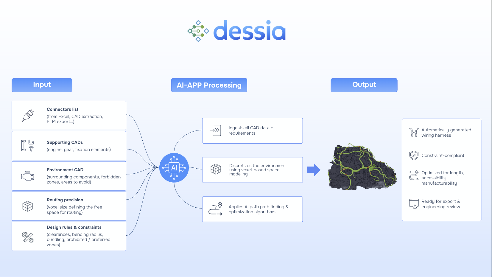
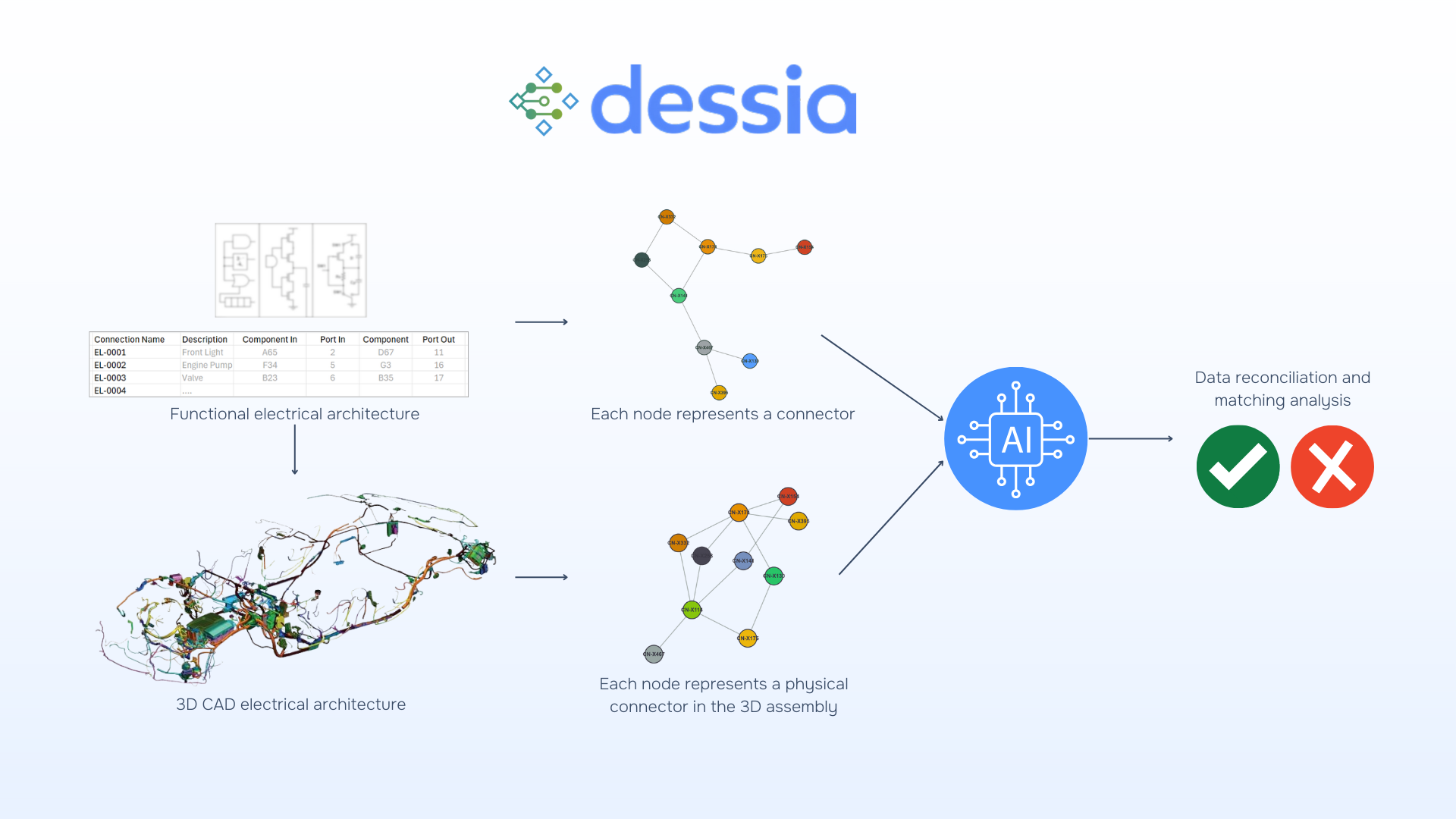
Thanks to Dessia’s AI-libraries, an AI-driven graph-based methodology can be used to bring determinism into data reconciliation. The key principle: both Excel/eCAD definitions and mCAD assemblies can be expressed as graphs, making them comparable in a systematic way.
1. Reference graph creation (from Excel/eCAD)
- Functional definitions (wires, connectors, components) are parsed.
- A reference graph is generated, where nodes represent elements and edges represent relationships.
- This graph is stored as a baseline for comparison.
2. CAD graph extraction (from 3D CAD assemblies)
- The physical electrical architecture is processed to extract connectors and harness structures.
- A CAD graph is built to mirror the structure of the reference.
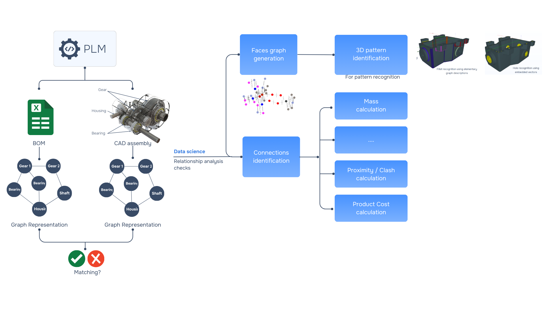
3. Graph matching and verification
- Deterministic algorithms compare the two graphs.
- Discrepancies are identified in wire counts, merges/splits, and component mappings.
- Results are traceable back to the exact data sources.
4. Reporting and visualization
- Correspondence tables show alignments and mismatches.
- Discrepancy reports highlight inconsistencies for review.
- Graph visuals give engineers an intuitive view of differences.
- Each output is linked to file versions and rules, ensuring full auditability.
A modular two-workflow system
To make the process efficient and scalable, the approach is divided into two workflows:
- Workflow 1: Excel Architecture Analysis
- Parse Excel/eCAD harness definitions.
- Build and store the reference graph.
- Generate extraction reports and 2D visuals.
- Workflow 2: CAD Analysis & Graph Matching
- Extract harness data from CAD assemblies.
- Compare against the reference graph.
- Generate CAD graph visuals and discrepancy reports.
This modular design ensures flexibility: Workflow 1 runs whenever functional data changes, while Workflow 2 runs with each CAD update. Together, they create a living digital thread between design intent and physical embodiment.
Beyond electrical architecture: An industry-wide need

This challenge of scattered , inconsistent data is not unique to one company or to electrical architecture. Across industries - from automotive to aerospace to heavy vehicles - functional definitions ( Excel, eCAD, requirements) and physical assemblies ( MCAD, BOM, system models) are often managed in silos. This separation inevitably creates data drift over time, making reconciliation a manual and error-prone effort.
To address this, engineering teams need scalable ways to structure and reconcile fragmented data, ensuring that information remains coherent across tools and teams. By combining data structuration with AI-driven verification, organizations can achieve outcomes that every sector demands:
- Consistency across the digital thread
- Continuous compliance
- Design efficiency through knowledge reuse
- The ability to explore new designs and architectures with confidence
Conclusion
The challenge faced in this case is emblematic of a wider reality in engineering today : as systems grow in complexity, data is created and maintained in silos — Excel, eCAD, CAD, PLM — and the responsibility of keeping them consistent often falls on manual, error-prone effort. The cost is hidden but huge : wasted engineering hours, delayed programs, and quality risks that can surface far too late.
By turning these data sources into comparable and automating the verification process, Dessia showed that consistency can be engineered, not just checked. Instead of being a late-stage control, data alignment becomes a continuous, auditable process embedded in every design iteration.
This shift matters beyond electrical harnesses. It represents a broader way forward for industry : using computational methods to bridge functional intent and physical realization, to catch errors where they start, and to free engineers to focus on innovation rather than reconciliation.
As engineering moves toward ever more digital, interconnected systems, approaches like this will be critical to ensuring that complexity remains manageable, trustworthy, and certifiable at scale.
Keep exploring - Discover more case studies
AI for Knowledge Reuse
9
min reading