AI powered architecture generation for thermal systems - functional approach
With Dessia’s AI libraries, design engineers generate and evaluate HEV cooling system architectures to optimize energy, thermal control, integration, cost, and layout.
Hybrid Electric Vehicles (HEVs) introduce a unique engineering challenge: they generate heat from both internal combustion engines and electric components, each operating at different temperature ranges. As a result, their cooling systems must manage multiple heat sources simultaneously, often requiring several independent thermal loops. Unlike traditional vehicles, there's no one-size-fits-all architecture for HEV thermal management. However, clear trends—like the widespread use of liquid cooling for batteries—are emerging.
In this case study, we explore how Dessia’s AI Libraries enable the automated generation, evaluation, and optimization of functional cooling architectures for HEV powertrains. This method allows for early architectural decisions that directly influence energy efficiency, emissions, and cost.
1. Powertrain system and cooling subsystem integration in HEVs
Hybrid vehicles have additional heat sources, and their components operate over different temperature ranges. The cooling system must be able to regulate the temperature of the various vehicle components, which often requires multiple cooling loops. There is no universal architecture for cooling systems, but it is possible to identify macroscopic trends, such as the use of liquid cooling solution for batteries. According to the system modeling approach, the system here is the HEV powertrain system and the cooling system is one of the subsystems.
The image below illustrates the decomposition into system and subsystem of an HEV vehicle as used in Dessia's system modeling approach described in this document. At the Powertrain system level, the choice of its functional architecture, as well as its dimensioning and the control of its components, allow the definition of the requirements for the cooling subsystem. From these requirements, a functional architecture of the cooling subsystem is identified, as well as the dimensions and control of the different components (pumps, radiators, etc.). The functional architecture defines the arrangement of the different components and the number of independent loops (i.e., the topology).

The results of the powertrain and cooling subsystem design allow for the evaluation of the main vehicle level objectives, i.e. energy consumption, CO2 emissions and cost, while respecting the integration constraints. Control of the actuators (i.e. hydraulic valve(s), pump(s), etc.) is important to meet the requirements and optimize the objectives.
2. Functional breakdown of components in HEV cooling systems
With Dessia's system modeling, the cooling system of an HEV vehicle can be broken down as follows :
Components to be cooled or heated :
- Internal combustion engine
- Electric machine
- Battery, etc..
Components capable of supplying or capturing heat :
- Radiator
- Aerotherm (exchanger allowing to regulate the temperature of the passenger compartment)
Components capable of moving a heat transfer fluid :
- Hydraulic pump
Components capable of transporting heat :
- Hydraulic hose
- Hydraulic junction Tee
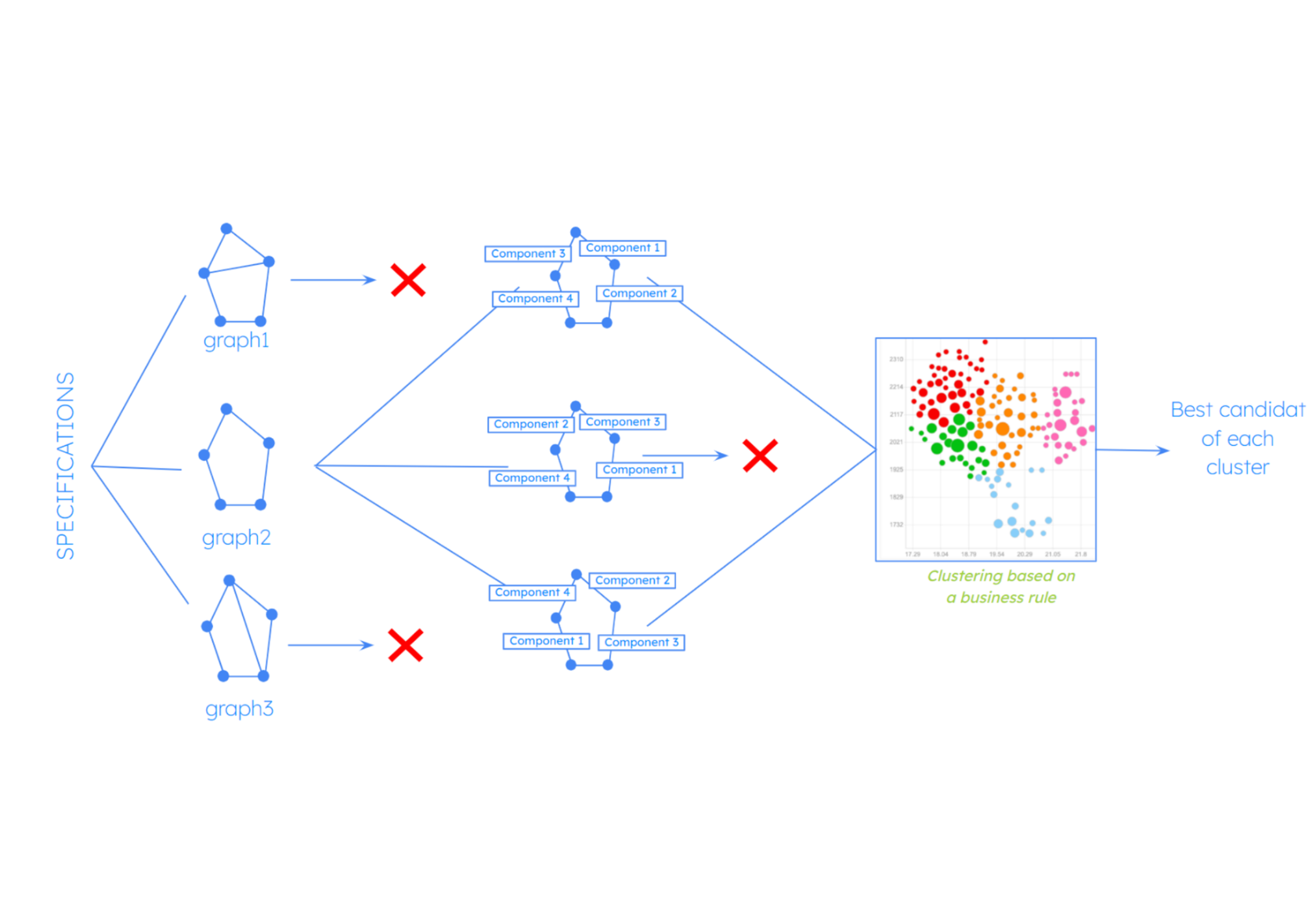
The definition of the interfaces (number of possible hydraulic inputs and outputs) of each of these components allows to generate, via a generative algorithm, the set of possible combinations of connections between these components. Each combination can be represented as a graph. The image below shows three different possible graphs allowing to connect the different electrical components of the hybrid drive train. Solutions (a) and (b) represent architectures where the components are connected in series with different permutations. In solution (c) the two components battery and charger are positioned in parallel, which can improve the permeability of the circuit.

High temperature circuit architectures regrouping the thermal components of the HEV drive train are presented in the illustration below. It is possible to play on the number of pumps present in the circuit to optimize the thermal management. Solution (c), for example, uses a second pump around the heater to heat the passenger compartment in the electrical phase (no heat input from the ICE) via an immersion heater (PTC).

3. Simplified sizing, control strategies, and performance evaluation
For each functional architecture generated, the choice of sizing and control of the components characterizing the thermal system (especially pumps and radiators) allows to estimate the energy performance as well as the cost of the solution.
Simplified sizing and control is generally preferred when looking for a design solution. Simplified hydraulic pump and radiator sizing is often based on energy performance maps.
A rule-based control is commonly used to define a simplified control. In an HEV vehicle cooling system application, a rule-based control can drive the flow of coolant through the various branches of the system.
The flow distribution can be based on thresholds defined by system state variables, such as:
- Coolant temperature
- Internal combustion
- Engine speed
- Battery state of charge
- Cabin heating demand etc.
For example, for solution (c) different circuit configurations can be obtained depending on the cabin heating demand and the coolant temperature. The configuration c1 can meet a cabin heating demand when the coolant temperature is low (i.e. during the ICE warm-up phase). Then the configurations c2 and c3 allow to regulate the coolant temperature.
.png)
Conclusion
In conclusion, this section has described how Dessia's AI Libraries can be applied to the research and evaluation of functional architectures for HEV cooling systems. The evaluation step allows for the pre-selection of functional architectures to be retained for the rest of the design process of cooling systems for hybrid vehicles, namely the 3D architecture and the technical specifications of the components.
The search for 3D architectures consists in exploring the possibilities of placing the various components and hydraulic circuits in an allocated volume. The technical specification consists, for example, in defining the valves allowing the realization of the different circuit configurations.
Finally, the presented method can also be applied to the research of cooling systems for electric vehicles (BEV). Indeed, the large number of components to be cooled or heated (battery, DCDC, inverter, charger, electrical machines, etc.) as well as their authorized temperature range makes the design of a cooling system for a BEV very complex.
Keep exploring - Discover more case studies
AI for Knowledge Reuse
9
min reading